GPIO Driver sample
Using this GPIO driver, the LED on the Development Board will blink. The sample application is available in Blinky sample.
Explain the sample code
Directory Name
The directory name and structure for the sample application can be chosen freely.
In this example, we use the directory name samples/blinky.
CMakeLists.txt
A CMakeLists.txt file must be placed directly under the application directory.
# Copyright (c) 2025 Space Cubics Inc.
# SPDX-License-Identifier: Apache-2.0

cmake_minimum_required(VERSION 3.20.0)

find_package(Zephyr REQUIRED HINTS $ENV{ZEPHYR_BASE})
project(blinky)

target_sources(app PRIVATE src/main.c)
Here, the parts that need to be modified for each application are explained.
-
project: Specify the desired project name -
target_sources: Specify the source code files
prj.conf
Additional Kconfig parameters required for running the application can be specified.
As this example uses GPIO, it is necessary to set CONFIG_GPIO=y.
CONFIG_GPIO=ySource code
The source code is shown below. Details will be explained separately.
/*
 * Copyright (c) 2025 Space Cubics Inc.
 *
 * SPDX-License-Identifier: Apache-2.0
 */

#include <zephyr/drivers/gpio.h>

int main(void)
{
	int ret;
	const struct gpio_dt_spec led = GPIO_DT_SPEC_GET(DT_ALIAS(led0), gpios);
	int led_state = 0;

	if (!gpio_is_ready_dt(&led)) {
		printf("GPIO device is not ready\n");
		ret = -ENODEV;
		goto end;
	}

	ret = gpio_pin_configure_dt(&led, GPIO_OUTPUT_ACTIVE);
	if (ret < 0) {
		printf("Failed to configure a GPIO pin (%d)\n", ret);
		goto end;
	}

	while (true) {
		ret = gpio_pin_toggle_dt(&led);
		if (ret < 0) {
			printf("Failed to toggle a GPIO pin (%d)\n", ret);
			goto end;
		}

		led_state = gpio_pin_get_dt(&led);
		if (led_state < 0) {
			printf("Failed to read GPIO state (%d)\n", led_state);
			goto end;
		}
		printf("LED state: %s\n", led_state ? "ON" : "OFF");
		k_sleep(K_SECONDS(1));
	}

end:
	return ret;
}
GPIO Device structure
The SC-OBC Module A1 is equipped with AMD (formerly Xilinx)'s AXI GPIO IP core, which connects to 10 GPIOs.
The relationship between the GPIOs and the User IO pins is as follows, with GPIO15 connected to the LED11 on the Development Board.
| User IO pin name | GPIO name in AMD GPIO IP core |
|---|---|
UIO2_15 |
GPIO15 |
UIO2_14 |
GPIO14 |
UIO2_13 |
GPIO13 |
UIO2_12 |
GPIO12 |
UIO2_11 |
GPIO11 |
UIO2_10 |
GPIO10 |
UIO2_09 |
GPIO9 |
UIO2_08 |
GPIO8 |
UIO2_07 |
GPIO7 |
UIO2_06 |
GPIO6 |
Referring to the DTS overlay file for Development Board, it can be seen that GPIO15 of the GPIO IP core is defined with the device name user_led_0.
Additionally, an led0 is assigned using the alias, which is used by Zephyr’s Blinky sample. However, this alias is not mandatory.
	aliases {
		led0 = &user_led_0;
		sw0 = &user_sw_0;
	};

	leds {
		compatible = "gpio-leds";
		user_led_0: led_0 {
			gpios = <&gpio0 15 GPIO_ACTIVE_HIGH>;
		};
	};
Therefore, in this example, the GPIO device structure is obtained using GPIO_DT_SPEC_GET and DT_ALIAS.
const struct gpio_dt_spec led = GPIO_DT_SPEC_GET(DT_ALIAS(led0), gpios);About GPIO_ACTIVE_HIGH
In the DTS overlay, the user LED is defined as:
gpios = <&gpio0 15 GPIO_ACTIVE_HIGH>;On the Development Board, the user LED is driven through an N-channel MOSFET.
When the GPIO pin drives the MOSFET gate HIGH, the MOSFET turns ON and current flows through the LED, causing the LED to light up.
Electrically, this means:
-
GPIO = 1 (HIGH) → LED ON
-
GPIO = 0 (LOW) → LED OFF
Therefore, the LED is considered active when the signal is HIGH, which is why
GPIO_ACTIVE_HIGH is used in the Device Tree configuration.
The User LED driving circuit is something like this:
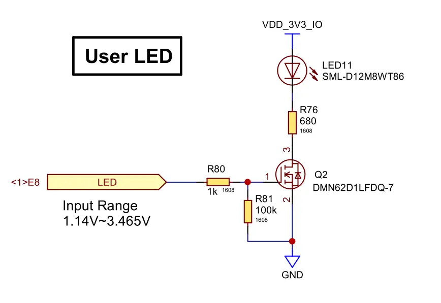
You can check the Development Board schematic at Design Information (see the LED control circuit in the schematic document):
This configuration allows Zephyr to interpret the GPIO value correctly, so that a logical 1
corresponds to the LED being ON and 0 corresponds to the LED being OFF.
Validate that GPIO port is ready
Validate that GPIO port is ready. If the GPIO device is not properly initialized, it will return false.
	if (!gpio_is_ready_dt(&led)) {
		printf("GPIO device is not ready\n");
		ret = -ENODEV;
		goto end;
	}
Configure a GPIO pin
The GPIO is configured to its initial state as OUTPUT_ACTIVE. If the configuration fails, a negative value will be returned.
	ret = gpio_pin_configure_dt(&led, GPIO_OUTPUT_ACTIVE);
	if (ret < 0) {
		printf("Failed to configure a GPIO pin (%d)\n", ret);
		goto end;
	}
Toggle a GPIO pin
Toggle the GPIO pin. If the toggle fails, a negative value will be returned.
	ret = gpio_pin_toggle_dt(&led);
	if (ret < 0) {
		printf("Failed to toggle a GPIO pin (%d)\n", ret);
		goto end;
	}
Read GPIO state
In this sample, the LED state is read back from the GPIO after toggling it.
gpio_pin_get_dt is used to read the logical level of the GPIO pin.
If the read operation fails, a negative value is returned.
led_state = gpio_pin_get_dt(&led);
if (led_state < 0) {
    printf("Failed to read GPIO state (%d)\n", led_state);
    goto end;
}
Open console
Connect the cable between your SC-OBC Module A1 and your PC, then open the console in a terminal:
tio /dev/ttyUSB2| To use the Zephyr console, bit3 (RX) and bit4 (TX) of DIP Switch (SW1) must be turned ON. If they are currently OFF, please switch them ON. |
Build
Specify the sample application directory where CMakeLists.txt and prj.conf are placed, and then build as shown below.
cd ~/myproject
source .venv/bin/activate
west build -p always -b scobc_a1 --shield scobc_a1_dev scobc-a1-sample/samples/blinkyConfirm
After power-cycling the SC-OBC Module A1, you should see that the LED11 will blink on and off every second, and the LED state will be displayed on the console.
*** Booting Zephyr OS build 60e8eb54f7ae ***
LED state: OFF
LED state: ON
LED state: OFF
LED state: ON
If you want to exit the tio console, first press Ctrl + t, followed by q.